 Business
Object Workshop III
 Business
Object Workshop III
Modelling Domain Specific Application Frameworks with a Dynamic Business Object Architecture: An Approach and Implementation
Kitty Hung1 and Dilip Patel2 School of Computing, Information Systems & Mathematics South Bank University 103 Borough Road, London, SE1 0AA, UK Email: 1 hungks@sbu.ac.uk 2 dilip@sbu.ac.uk URL: http://www.scism.sbu.ac.uk/cios/hungks
ABSTRACT: This paper describes the approach of a Business Object Architecture (BOA) development and implement it through a Dynamic Systems Development Method (DSDM) life-cycle environment with emphasis on end-user's involvement and iterative prototyping. The Dynamic Business Object Architecture (DBOA) is used for supporting and embracing the conceptualisation and design approaches for specific application domains. Distinctively, the DBOA is treated as skeletal support and life-cycle basis for OO modelling construction. This paper is in response to assist the review of the initial submissions of OMG BODTF's RFP for Common Business Objects and Business Object Facilities (BOR FP1) to model domain specific application frameworks.
KEY WORDS: Business Object Architecture, Life cycle, Domain Specific Application Frameworks
1. INTRODUCTION
Information plays a crucial role in the business organisations. It has become an asset to organisations in their corporate strategic management planning. An efficient information system can no doubt assist organisations in improving their business performance. Object-orientation (OO) has gradually been adopted by more organisations to combat more complexity problems and to cope with the frequent changes of business. However, the adoption of OO has posed a challenge to both software practitioners and the business management in terms of the missing link between the business end-users and the IT developers. Although there are publications describing the benefits and development guidelines of Business Objects [Sutherland95]; [Hertha95], [Shelton96], [Ramackers95], [Digre96] to tackle the missing link problem, the strategies proposed only see the business from the IT developers' pair of "tinted glasses" with the developers see the business from their own perspective. The end-users are denied of having the access to this pair of "tinted glasses" to be informed of or to participate in the development. Business people are most fitted as the knowledge providers and system responders in the system development. The approach of this paper is to expand the Business Object technique to form Business Object Architecture (BOA) [Casanave95] and implemented it in a Dynamic Systems Development Method (DSDM) life-cycle environment [DSDM95] [Stapleton97]. The DBOA developed in this paper is a business driven model with a strong emphasis on business enterprise activities and processes as well as feedback from the end-users.
Section 2 of this paper describes the formation of business objects. Section 3 addresses the problems and weaknesses of business objects in handling multiple applications and complexity management. Section 4 suggests the BOA approach. In Section 5, a Dynamic Business Object Architecture (DBOA) framework is presented applying the BOA coupled with the DSDM life cycle. The structure and process of the DBOA are explained through the development work documented in this paper. In Section 6, a case study report is presented to demonstrate the initial result of this approach. Finally, the evaluation of the case study with some insights resulting from applying the DBOA techniques is discussed in Section 7 followed by conclusion and future work of our approach.

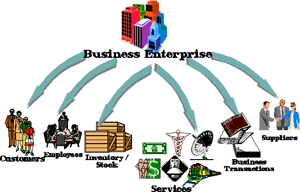
Figure 1 : Business Objects within the Business Enterprise
If we want to develop business objects, we must understand the business first. Figure 1 shows that within a business enterprise business objects can be extracted from customers, employees, inventory/stock. Business objects can also be established in servicing industry like banking and finance, insurance, catering, transportation and telecommunication. The main difference between business object and software programming object is that instead of describing the attributes, behaviour, operations, we firstly define the impact of this business object in that particular business. For example, in a customer business object, we have the name, address, telephone no, and contact person details for that customer. However, this is not enough. In a customer business object we also want to define the credit rating of that customer, how long ago did this customer place his or her last order?. Is there any outstanding bill? What kind of products or services this customer requires from us? Is there any trading risk?. In other words, a customer business object describes the business profile of the customer, which includes how we process the customer's order, enquiry or complaint and how we serve the customer. In a business object, everything is described in one single model. At the moment, there is no standard way to create a business object but we have adopted Jacobson Use Case Engineering [Jacobson94] and Ramackers' Business Domain Object technique [Ramacker95]. We use the Event diagram, which gives an overview of the business processes. Then an Interaction Diagram like a flowchart to describe the business processes step-by-step. The Use Cases and Actors bring out the names of the tasks and how to perform them. This Use Cases & Objects diagram converts data into entity object, process into control object and actor into interface object. So we have 3 different kinds of objects playing different roles. Once we have converted business use case to business object, we then use Ramackers' Business Domain Object model to visualise all components and relationships within a business object. Then we move on to object and class diagram. The developer can then generate the database necessary to support implementation of the application.
Problems of business objects are that when it comes to complexity management, no single definition of a business object can serve all purposes. One business object has only a single interface definition and is unable to take different points of view [Daniel96]. If we develop business objects one-by-one and put them together inside a business domain, we will end up with object redundancy and object overlapping [Hung97(b)]. In reality, we always face a situation that in a business organisation, different business operations might share common processes, tasks or objects. For example, when we handle invoicing and insurance claims, we need to deal with customers. Does it mean than we need to include the customer details in both the invoicing business and insurance claim business objects? If so, we are overlapping the business objects. If not, how do we share the same business object? Moreover, we also need workflow direction to describe different business operations within an organisation.
The weaknesses of business objects have prompted the adoption of an "Architecture" approach. Business Object Architecture as defined by OMG Business Object Domain Task Force that it is: "To represent the components that are used to model the business problems and build the system" [Casanave95]. In this paper, our approach to the development of BOA Model is to adopt both a top down and bottom up directions as shown in Figure 2.

Figure 2 : Business Object Architecture
After defining the business processes from a high level, we then identify all the necessary entity objects from bottom up. Finally, we develop the business objects integrating the business processes, the functionalities and operations together. Those business objects do not hold the entity objects. Instead, they call the entity object when they want to use them. The entity objects still stay in the same level at the bottom of the framework. A single entity object is shared by different business object. So when we want to change the attributes of the entity object, we only have to change once. Another benefit of the BOA Framework is that not only we can reuse the entity objects but also we can reuse the business object as a package. We can reuse the business processes as well.
Research work on using Architecture Framework to model business has been published [Hertha95]. However, there is still a missing link between the business end-users and the IT developers in the current approach. If the BOA is used to model the domain specific application frameworks, we need to confirm with the domain experts on the effectiveness and responsiveness of the BOA. The holistic approach of the DSDM Life-cycle has provided an ideal environment where we can involve the end-users in the system development through the Joint Requirement Planning (JRP) and Joint Application Development sessions (JAD). The Usability Testing in the prototyping session is to get the feed back from the business end-users. The iterative prototyping approach also enables us to start a new life cycle to revisit and change the previous model.

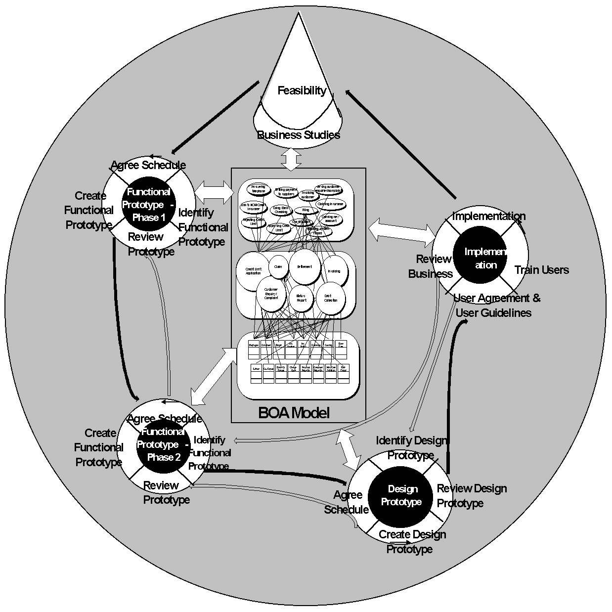
Figure 3 : Dynamic Business Object Architecture
The development of a Dynamic Business Object Architecture (DBOA) as shown in Figure 3 is an integration between a Business Object Architecture implemented under a Dynamic Systems Development Method life-cycle environment with a strategy of business object reuse [Hung97(a)]. In the above diagram, the BOA is situated in the centre of the DSDM life-cycle model. Among each life cycle, there is an incremental prototyping approach through these phases moving anti-clockwise for the top with feasibility studies, 1st phase functional prototype, 2nd phase functional prototype, design prototype iteration and implementation phase. Black arrows show the transfer points from one phase to another and the grey ones show where the development can easily return to an earlier phase. The white arrow indicates that the BOA model can always be re-architectured at any stage of the life-cycle.
We used a case study to test the DBOA model. It is the development and implementation of a 'Major Debtor Profile' system in a Credit Insurance Agent business organisation.

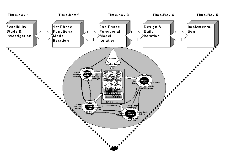
Figure 4 : Time-boxing for Major Debtor Profit System
As shown in Figure 4, Time-boxing is also a part of the DSDM approach. Each time-box has a set duration and tasks. The purpose to set time-box is to form a good control to deliver project on time and within budget.
6.1 Time-box 1 : Feasibility Studies and Investigation (5 days)
The initial JRP meeting with the users was to get to know the user requirements for this particular project; how they wanted to develop the Debtor Profile system. The project provided quite clear-cut requirements, in the technical context of a general need to provide information on all the current debtors for a particular customer. The Debtor Profile Interface is in fact a consolidation of different database files such as Customer, Buyer, Credit Insurance Policy, Country, Currency and Exchange Rates. The Debtor Profile system correlates relevant data fields from different database files to the debtor Profile Interface. When the users enter the customer reference number, this customer reference number data field will trigger other correlative data fields to display all the existing debtors' details for that customer as well as the insured limit where CAD's customer is allocated to each buyer. Over and above these features, the end-user can also view a profile by currencies, countries and period etc. This Debtor Profile system is to assist the end-user in making decision making whether to approve or reject any future credit insurance application for a particular buyer. During this feasibility studies, object and class diagrams were generated based on our BOA framework model. The objective of the first phase functional model iteration was to produce a version of the working system, designed using Unified Modelling Language (UML) methodology [Rational97] and the interface was constructed using System Builder Plus [SB+] 4GL GUI Tools that could demonstrate to the user the essential features required to enable a Debtor Profile to be constructed.
6.2 Time-box 2: 1st Phase Functional Model Iteration (5 days)
The objective of the first phase functional model iteration was to produce a version of the working system, from analysis and design model, notation to implementation, that could demonstrate to the user the essential features required to enable a user view the debtor profile. The first day was spent developing aspects of the model using UML to created object, class, event trace and state transition diagrams. Data dictionary documentation was also produced. The second day was used for discussion and modification of the model, within the IT Department (i.e. without the involvement of any users). By the third day we could begin to map the UML design to SB+. The emphasis at this stage was on the development of data fields and the associated screen handling. This was no more than a 'rough' prototype, but it was able to demonstrate the essential features of the interface and some of the functionality of the new system. The fourth day comprised another 'IT internal' review; this time to test the prototype. A range of modifications and improvements were made, with suitable care to ensure that the UML model was maintained consistent with the SB+ implementation. Finally for this Time-box, the fifth day was spent in JAD session, reviewing with the users the prototype. It was necessary to involve users engaging in both management (the ambassador users) and clerical positions (the day-to-day users) as the prototype is in fact a work model to pave the way for future project development. Even at such an early stage, decisions were required from the users in determining whether the prototype was suitable to meet the business requirements. The objective of this JAD session was to give a feel to the end-users for what the Debtor Profile interface looked like. As the correlation was not set up yet, the end-users could not test the linkage. At this stage we had not attempted to transfer the data from different data files to the Debtor Profile file. We just wanted to show to the end-users the layout of the interface and whether there were any data fields missing.
Requirements were recorded as the tasks for the next time-box. As the new requirements were within the time scale, no developer hour was added to the Function Point Table. However, The IT Department staff would determine whether the change of requirements could be achieved within the Time-boxes or not. If so, IT staff would change the design and update the 'Function Points Table' accordingly. If not, the Project Development Team would negotiate an extension to the project deliverable deadline.
6.3 Time-box 3: 2nd Phase Functional Model Iteration (5 days)
The main objective of this second phase of the development of the functional model was to provide the bulk of the essential functionality to the model. The first phase had been mainly concerned with user interface design, with little in the way of 'business functionality'. An important issue of this early work in phase 2 was to revisit the BOA framework and its break down to find out whether the conceptual model framework was the right shape to drive through to deliver business systems/applications. We used the BOA conceptual model to pave the way for the system analysis, design and implementation. On the other hand we brought back changes made by the business end-users to re-architecture the BOA model. Such cycle goes iteratively so that we could check our model almost instantly. The first day was spent in creating a first cut design for the second phase functional prototype A meeting within the IT Department was held on the second day to discuss progress and modification. Much care had to be taken to keep adequate records of what could become a quite frantic rate of change unless careful controlled the project leader. Version control was a very real issue. The third day was spent in modifying the first phase functional prototype based on the feedback from the end-users and the conclusion reached in the previous day's meeting. On the fourth day, a session was held within the IT Department to review and test the second phase functional prototype. On the fifth and final day of Time-box 3 a project team meeting was held and the end-users tested the refined prototype. By this stage in the Time-box the changes were less significant, and to a large extent the session was more involved with user familiarity, identifying only minor points to take back to the next phase.
6.4 Time-box 4: Design and Build Iteration (5 days)
The schedule in Time-box 4 was similar to Time-box 3. However the essence of this phase is that we must design and actually build the system. Hence by the end of this phase the system must contain absolutely all functionality, in a form which is suitable for testing in the final JAD session. There should be no components of functionality left un-implemented if the schedule is to be met. This time the link between all relevant data fields from different data files was connected. The end-users could select a customer no. from the selection and when the end-user clicked the icon, the rest of the data fields were now being filled with details. The end-users could also choose the different styles of report from the menu arranged by the order of customers, countries, buyers, currencies or period. The JAD session revealed several further minor changes such as tidying up the positions of the data fields and the marginal setting of the report format. The IT Department facilitator was able to make these amendments during the JAD session. After the meeting, the prototype was transferred to a release version for implementation in Time-box 5.
The first day was spent in testing the system with the end-users which was purely to test the reliability and to debug the system. No extra requirements from the users were accepted within this Time-box. If the user had wanted to make further changes, we would have had to reschedule the project development life-cycle. The second day was to obtain end-users' approval and the third was to prepare and issue User Guidelines. The third and fourth days were spent in organising training programmes to show the end-users how to use the new system properly. On the fifth day which was also the final day of the project phase, file conversion and data take-on were done before 9:00am. The new Debtor Profile system interface went live.
As a result, project was delivered on time. User community seemed satisfied with the new application. There had been a complete team spirit between developers and end-users. The change of relationship from supplier/consumer to partnership had made software project more like a business project with developers sharing ownership of the project. The holistic approach of DBOA also enabled developers to understand business better thus bridging the semantic gap between business and I.T. The iterative life cycles allowed the developers to rearchitecture the conceptual model during the entire project phases.
So, is DBOA a silver bullet? Unfortunately not. There are some outstanding issues which need to be tackled such as the friction between developers and end-users. What to do if they don't get along with each other. Another issue is the time-boxing syndrome. What if we are stuck in time-box 2, should we move on and ignore the problem? Or should we solve the problem first before moving on? It is a catch 22 situation. Both the developers and end-users also face work pattern and paradigm shifts. Sometimes neither the developers nor the end-users like to cross the boundary to get involved in some duties which they think is beyond their scope of expertise and knowledge. Other future research work will include the development of an Object Repository and Reuse Library for managing reuse through CASE tools and the interaction between individual projects and the DBOA. The DBOA model will be used to handle complexity management through multi-threaded problem domain case studies.
[Casasnave95] Casanave,C. "Business Object Architectures and Standards" in the Proceedings of OOPSLA'95 Conference Business Object Design & Implementation Workshop I", Austin, Texas, October 1995. Springer, London, pp 7-28.
[DSDM95] DSDM Consortium. Dynamic Systems Development Method V. 2.0. Tresseract Publishing, Surrey, UK, 1995.
[Hertha95] Hertha, W, et al. "An Architecture Framework: From business Strategies to Implementation" in the Proceedings of OOPSLA'95 Conference Business Object Design & Implementation Workshop I", Austin, Texas, October 1995: Springer, London, pp47-60.
[Hung97(a)] Hung, K & Linecar, P. "Experience in Developing a Small Application Using a DSDM Approach" in the Proceedings for the British Computer Society SQM'97 Conference, Bath, UK, 22-24 March 97, pp165-178.
[Hung97(b)] Hung, K, Sun, Y & Rose, T. "A Dynamic Business Object Architecture for an Insurance Industrial Project" in the Object-Oriented Information Systems (OOIS) '97 Conference, 10-12 November 1997, Brisbane, Queensland, Australia.
[Jacobson94] Jacobson, I. et al. The Object Advantages: Business Process Reengineering with Object Technology. Addison-Wesley, NY, 1994.
[Ramackers95] Ramackers, G & Clegg, D. "Object Business Modelling, requirements and approach" in the Proceedings of OOPSLA'95 Conference Business Object Design & Implementation Workshop I", Austin, Texas, October 1995. Springer, London, pp 77-86.
[Rational97] Rational Corp. Unified Modelling Language (UML) Version 1.0. Rational Corporation, Santa Clara, CA, 1997. Source: http://www.rational.com.
[SB+] System Builder Technology UK Ltd. SB+ Version 2.3 Developer and Administrator Guide. System Builder Technology UK Ltd., Prestbury, UK, 1995.
[Shelton96] Shelton, R et al. OMG Business Application Architecture White Paper. OMG Business Object Management Special Interest Group (BOMSIG). Source: http://www.omg.org.
[Stapleton97] Stapleton, J. DSDM: The Method in Practice. Addison-Wesley, London, UK, 1997.
[Sutherland95] Sutherland J. "The Object Technology Architecture: Business Objects for Corporate Information Systems" in the 1995 Symposium for VMARK Users, Albuquerque, USA, 1995. Source: http://www.tiac.net/users/jsuth.
 Business
Object Workshop III